The above 3D Images were created and rendered whilst at Glass Canvas Productions
Lighting a scene realistically is one the most
challenging aspects of producing photorealistic renders.
The following article/tutorial will focus mainly in easy techniques to help users achieve acceptable results,
even when working on relatively bare/simple scenes.
One of the preliminary steps often taken to light up a scene
realistically, is to create a clear definition between dark and bright areas:
Depth.
To achieve this, simply ensure that, there’s enough distance
between each light in the scene.
Also, test render the effect of each light created,
especially when a key parameter is changed.
In mental ray- It’s common practice to
create photometric Target lights in
the Left or Front viewport to set its directional point (e.g. downwards).
Once the first light had been created, go to the Modify command panel and set its shadow type to Ray Traced Shadows, to enable mental ray to trace shadows more
accurately.
Also, the distribution type is often set to photometric web, followed by locating
and choosing the appropriate IES web file.
Once the light is created, one should remember to disable
the Targeted function. This action
will later prove crucial when copying /instancing lights across the scene.
While it may take slightly longer to render, soft shadows
are commonly used to make the renders look more realistic. To create soft
shadows simply scroll down to the Shape/Area
shadows rollout parameters and change the Emit light from (shape) to Disc
type.
Its Radius
controls the shadows’ softness: Sharp shadows= low values; Soft shadows= high
values.
To control its intensity, simply open the Intensity/Color/Attenuation rollout,
and pan down to Dimming group,
followed by enabling the Resulting
Intensity and increasing its value.
Test render each value tweaked to achieve the desired result.
To quickly test render, one can simply use a white override material
(with its reflectivity set to 0.0) for
the sole purpose of creating the correct amount of depth in scene (e.g. dark
and bright areas of the scene).
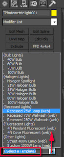
To use any specific IES light, one can choose from any of
the pre-defined (Select Template)
list; or by loading it from the Distribution
(Photometric) rollout toggle. One can preview the IES physical distribution
From the Open a Photometric Web file
dialog and/or from the Distribution
(Photometric) thumbnail.
Furthermore, users can also decrease the image Sampling Quality and the overall render
settings to speed up the test rendering process.
The idea behind this technique is to prevent users from
spending too much time test rendering the lights with all the materials and
reflections enabled.
Once satisfied,
simply begin to copy (instances), test render and place the lights accordingly
in the scene.
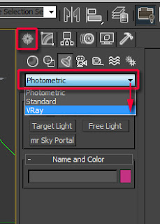
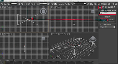
In Vray- Users often open the Create command panel and choose VRay from the drop down list.
Next, one can create the VRayIES light by simply selecting its respective button first,
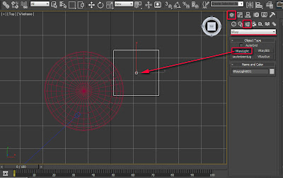
followed by clicking on the VRayIES
button next. Finally click in the Left or
Front viewport, and drag its target
downwards to create it.
Once the target of the light is set, go to the Modify command panel and disable its targeted function. As mentioned
earlier, this action will enable the user to easily copy/instance lights across
the scene.
Next, locate and load the appropriate IES light file by
clicking on its toggle. To preview the IES web file in the viewport, one can
simply create a default Max photometric light, turn it off and use its Distribution (photometric web) rollout for
the sole purpose of previewing the IES web file inside 3Ds Max.
Alternatively, one can use the IES generator software.
To help pick up tiny shadows (e.g. grass, etc.), one should
reduce the shadow bias values.
As mentioned earlier, while soft shadows may increase the
render times slightly it will also help make the renders more realistic.
To enable soft shadows with VRayIES lights, simply do the following:
Open the notepad
dialog by typing in the word notepad, on
the windows start up text field.
Next, locate the relevant IES file in your computer folder,
followed by dragging and dropping it into the notepad dialog. Its numerical
values should appear.
To soften the shadows, one should only change three of its
values. These values are often the three zeros that appear after the numbers 1,
1 and 2.
Change those three
zeros to 0.5; 0.5 and 0.5.
It’s worth noting that, the suggested values work well for
my scenes. However, feel free to experiment with different values, if desired.
To control its intensity, simply increase its power values.
As mentioned earlier, users should test render each value
tweaked to achieve the desired result.
As in mental ray, one can also use a white override VRay material (with its reflectivity
set 0.0) for the sole purpose of creating the correct amount of depth in scene
(e.g. dark and bright areas of the scene).
To further decrease the rendering times whilst test
rendering the lights in Vray, simply decrease the Sampling Quality and the overall render
settings.
As previously mentioned, the idea behind this technique is
to prevent users from spending too much time test rendering the lights with all
the materials and reflections enabled.
Once satisfied, simply begin copying, test render and place the
lights accordingly in the scene.
Test rendering each light created with Vray or mental ray will
enable users to preview their effect in the scene, and subsequently tweak them further,
if necessary; thus preventing the common mistake of overexposing/scorching the
3D scene with too many lights, and/or having the lights too close from one another.
It’s worth noting that, prior to lighting up a scene, most
materials and their basic parameters (e.g. UVW Mapping, etc.) should be applied
to their respective objects first.
While creating the correct amount of depth in scene will
help make the renders more believable, the light colours will also prove even
more crucial in achieving that ultimate photorealistic look.
The following examples will help demonstrate how to quickly
apply realistic colours of a photo to a light source in both Vray and mental
ray.
In addition to applying IES lights to a scene, one can make
the renders look more realistic by picking colour/s of a real photo reference.
To do so, first load the relevant photo in the scene (e.g. Rendering > View Image File) .
Next, select a light and open the Modify command panel.
In mental ray,
scroll down to the Intensity/Colour/Attenuation
rollout.
Click and hold the Filter
Color swatch. Its Color Selector: Filter Color dialog
should appear.
Click on its sample
screen colour button and pick any part of the loaded photograph. To mix
colours, simply hold down the Shift
key and continue picking
In Vray, scroll
down, followed by selecting and holding its Color swatch to enable the Color
Selector: Filter Color dialog.
Click on its sample
screen colour button and pick any part of the loaded photograph. To mix
colours, simply hold down the Shift key
and continue picking.
In addition to picking and using the colours of a real
photo, production companies also use a blurred version of the same photo as
light source to help make the render more realistic.
It’s worth noting that, while this methodology is utterly
effective, it also increases the rendering times slightly.
In mental ray, to
create the additional light/s with a blurred map, simply create a new spherical
photometric light using some of the techniques covered earlier.
To change the light to Uniform
Spherical, simply open the Modify
command panel and expand its General
Parameters rollout.
In the Light
Distribution (Type) group, choose the Uniform
Spherical from its drop down list. This light distribution type will provide users
with the numerical value to be added later in the mental ray Light shader.
Next, scroll further down to the mental ray Light Shader rollout and enable its function.
Please note that once this function is enabled; all
the default light parameters are automatically switched off. So even when the
light is physically turned off the light shader parameters will still affect the scene.
To disable it, simply uncheck the Enable function.
To plug a light shader, simply click on its toggle, and double
click on the Light point type to
choose it from the Material/map Browser
dialog list.
To view its parameters, open the Material Editor dialog first by pressing the M button.
Next, drag and drop the light shader toggle into an empty
material editor slot; followed by choosing the Instance type, from Instance
(copy) Map dialog. Its parameters should appear on the material
editor dialog.
Most of its parameters are self-explanatory. Before plugging
a blurred map to its Color toggle,
enable the Shadows and the Attenuation function.
The Attenuation function
determines the furthest distance of the light source from its original point.
The Attenuation Start
value should always be 0.0,
unless there’s a specific requirement.
Users often use the Radius
values from the Shape/Area Shadows
rollout parameters to preview the Attenuation End value in the viewport, without having to test render.
VRay users can also use this value
to preview the size of the light source; followed by turning it off once
satisfied.
When using light sources to cast colours of a real photo
onto surfaces, users should always place the light/s in a position where it
will affect as many surfaces as possible.
For instance, in an interior scene it’s common practice to
place the light between the floor and ceiling of each floor. In addition, the
light should be slightly dimmed to prevent bleaching areas of the scene.
Its sole purpose should be to create colour variations in
the scene with a faint brightness; and to also break up even specular patterns.
Next, locate the relevant blurred image and load it in the Color toggle. When possible, always use
an HDR (high dynamic range)
spherical panoramic image. If the shot happens to be a photomontage, one should
seriously consider taking a panoramic photo of the environment in question.
Otherwise, one can simply use a standard non panoramic blurred
JPEG image.
To blur an image, simply open it Photoshop and use the Gaussian Blur filter. The reason for blurring
an image is to avoid having very well defined colour patterns, sharp shadows and
increased rendering times.
Once the image is loaded, if the original bitmap is panoramic,
change its Coordinates parameters to Environment type, and the mapping to Spherical Environment.
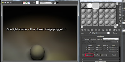
In addition, one can also decrease or increase its default Blur values to about 100. Blurring it to 100 will decrease
the rendering times dramatically.
Loading a sharp image and blurring
it in 3ds Max with the Blur function
will never yield good results. The rule of thumb is to load a pre blurred image
and blur it further in Max to 100, if necessary.
To control image intensity,
simply scroll down and open its Output
rollout parameters.
Also, increase its RGB Level value accordingly by test
rendering with the Material Override
enabled.
To clearly see the immense benefits of this methodology, the
following images will depict examples of a very simple scene lit without a
mapped image, with a mapped image, with an additional IES light source and an
IES light on its own.
In Vray, to
create a spherical light, one is required to first create a sphere primitive,
with the desired proportions.
Next, create a VRayLight
object using some of the steps covered earlier. Open its Modify parameters and choose the Mesh type from its dropdown list.
This light type will allow the user to plug a blurred image to its
toggle. See fig. 41 and 42
Scroll down to its Options
group and enable the following options:
Cast shadows
Invisible- This
function will make the light object invisible to the camera
Store with Irradiance
map- When using the light source as Mesh,
the rendering times will increase dramatically. Enabling this function will
help reduce the rendering times massively. Otherwise, one can disable it.
This function will only work if the Irradiance map is being used in the V-Ray:: Indirect Illumination (GI)
rollout parameters. For this reason, the
Irradiance map parameters should be set
above the minimum required.
Affect reflections-
This function is often disabled to prevent having the light being visible in
reflections.
While the above mentioned settings often work well in my
scenes, feel free to try different ones, if desired.
Scroll further down to the Texture group, and load the desired image in its toggle as
previously covered.
To view its parameters, simply open the Material Editor (M) first, followed by dragging and dropping the
toggle into an empty material editor slot.
Choose the Instance copy method, and use similar parameters to the ones covered earlier.
Choose the Instance copy method, and use similar parameters to the ones covered earlier.
If necessary use the Cropping/Placement handles to choose specific areas of an image to
be used as a light source.
It's also common to tweak with the "Bitmap" "Offset" coordinate values in "V" and/or "U" to help target specific areas of the bitmap.
It's also common to tweak with the "Bitmap" "Offset" coordinate values in "V" and/or "U" to help target specific areas of the bitmap.
Finally, scroll further down to the Mesh light options and select its toggle, followed by picking the
relevant mesh in the scene. Its intensity can be controlled through the image’s
RGB Level value, or/and from the
light’s Physical Multiplier value.
Note: When implementing the above mentioned technique using the VRay mesh light, the default "Sampling" "Subdivs" value of 8 may yield inaccurate/unrealistic shadows. To correct this, simply increase the "Subdivs" to 64.
While this value will produce realistic/accurate shadows, it will NOT increase the rendering times due to the "Store with Irradiance map" function being enabled. Furthermore, when sending the final render, the "Indirect Illumination" "Irradiance map " values need to be set to "Medium" or "High".
All the spherical lights depicted in the 3D scene below, were
created using the techniques highlighted earlier, for VRay and mental ray.
Note: If the bitmap colours emitted by the sphere light are not prominent enough in the scene, simply use the "Color Correction" procedural map on top of the main bitmap; and increase its "Saturation" value until satisfied.
To apply it, simply open the "Material/Map browser" dialog and choose it from its list. This topic was covered in this post HERE.
Alternatively, increase the saturation in Photoshop and re-save the main bitmap.
To implement the same technique to emulate interior studio
lighting or a light being emitted from a self-illuminated display screen,
simply create a VRayLight object.
To control its physical size, open the Modify command panel, scroll down to the Size group and tweak with its Half-length
and Half-width values.
To plug an image to the light, scroll down to the light’s Texture group and click on its toggle
to enable the Material/Map Browser
dialog.
In mental ray- To
emulate a similar effect in mental ray (e.g. Interior studio lighting or a
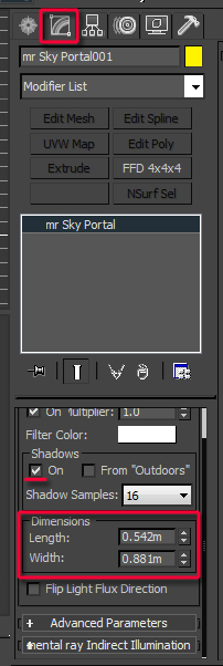
light being emitted from a self-illuminated display screen), simply create a mr Sky Portal object.
To control its size, open the Modify command panel, scroll down to the Dimensions group and tweak with its Length and Width values.
The mr Sky Portal is set to Use existing Skylight by default. This
option only works when a Skylight object
is already in the scene. The mr Sky
Portal helps to re-direct the Skylight
rays through where the mr Sky Portal
is positioned (e.g. through open windows, etc).
To use the mr Sky
Portal for interior scenes, one is required to enable the Custom function first, and click on its
toggle; followed by double clicking the Gamma
& Gain shader from the Material/Map
Browser dialog list.
To edit the Gamma
& Gain shader, simply open the Material
Editor first, followed by dragging & dropping it onto an empty material
editor slot. In the Instance (Copy)
dialog, choose the Instance method and OK
to close it.
Its parameters should load up. To plug a texture/HDRI simply
click on the Input toggle and locate
the relevant image.
Its multiplier value can be controlled through the Gain (multiplier) values; or
through the image’s RGB Level as
previously shown. In addition, one can
also use the mr Sky Portal’s On Multiplier value (1.0 by default)
to help bump up the intensity of the light.
The Reverse gamma
correction (De-Gamma) function is enabled by default; which means brighter
values are equivalent to high negative values. To reverse this, simply disable
it.
One can also control the Gamma values of the image by tweaking with the Gamma values. See fig. 57 and 58
All the rectangular lights depicted in the 3D scene below,
were created using the techniques highlighted earlier, for Vray and mental ray.
To emulate the Payless self-illuminated display screen on the right hand side; I have simply created an object with a Payless self-illuminated bitmap assigned to the object, and placed a rectangular light in front of it to emit rays of the same image using the techniques covered earlier.
To emulate the Payless self-illuminated display screen on the right hand side; I have simply created an object with a Payless self-illuminated bitmap assigned to the object, and placed a rectangular light in front of it to emit rays of the same image using the techniques covered earlier.
Finally, one can also use the same approach with Skylight objects, when creating external
shots.
In mental ray:
When using the Daylight System,
users often disable the Skylight option
and create a separate Standard one.
The Standard Skylight
object provides users with the flexibility to independently plug custom shaders,
colours and images to its toggle.
Alternatively, users can enable the Use Scene Environment option, to extract the sky data from the Environment Map toggle (press 8 to bring up its dialog).
For Photomontages and film shots, users often plug the Environment/Background Switcher shader
to its Environment Map toggle.
For further information about this shader, please check this
useful article HERE.
In Vray- Users are simply required to
create a standard VRayLight object
as previously shown, and change its Type
to Dome. Dome light is equivalent to Skylight object.
As with most VRay lights, users can control its intensity
with the Multiplier values.
To plug an image, scroll down to its Texture group and click on its toggle to bring up the Material/Map Browser dialog. Often some
users apply a standard image; and most professionals prefer to use the VRayHDRI shader.
To edit the VRayHDRI parameters,
first open the Material Editor (M), followed by dragging and dropping
it from the Texture toggle onto an
empty material editor slot. Choose
the Instance method.
Once the VRayHDRI
parameters are loaded, click on its Browse
button to locate and pick the relevant HDRI file.
While the Skylight shadows should yield diffused results,
some users prefer to turn off the VRaySun
object and use the Dome light to
generate both direct and indirect shadows (e.g. diffused shadows).
Most HDR images come with a reflection image (e.g. sharp),
and the environment image (e.g. blurred to emit diffused light). To generate
both direct and indirect shadows, one is required to use a sharp HDRI.
Users often tweak with Horiz.
rotation and Vert.rotation
values to control its position in the Material
Editor slot thumbnail.
Also, the Overall
mult. value will help control the brightness of the light/scene.
Depending on the results intended, most users choose the Map type to be a Spherical environment. For acceptable results, one is required to have
the Irradiance map and the Light cache parameters very high.
Furthermore, one should copy and paste/ instance these VRayHDRI parameters into the Environment Map toggle.
To override either the GI Environment (diffused light) or
what’s being reflected in the scene Environment
Map toggle; one should open the Render
Setup (F10). In the V-Ray tab,
expand the V-Ray:: Environment rollout and use one or both of its parameters(e.g. GI
Environment (skylight) override and/or the Reflection/refraction environment override).
Once the lights and colours have been signed off, one can
then disable the material override to finalize tweaking the materials/
reflections/glossiness, and perhaps fine-tune minor light settings (e.g. boost
up or decrease certain values).
The images below depict some of many results with Vray and mental ray produced
whilst using the techniques covered in this article.
3D Image created and rendered whilst at GMJ design ltd
3D Image created and rendered whilst at GMJ design ltd
I hope you have found this article interesting!


